|
|
|
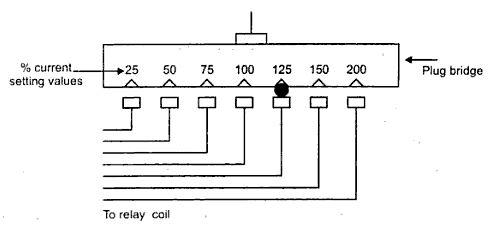
Fig.1 Tapping for current setting |
The
various terminologies
used in the protective relaying
1. Protective
Relay : It is an electrical relay, which closes its contacts
when an
actuating quantity reaches a certain preset value. Due to closing of
contacts,
relay initiates a trip circuit of circuit breaker or an alarm circuit.
2. Relay
Time : It is the time between the instant of fault occurrence
and the
instant of closure of relay contacts.
3. Breaker
Time : It is the time between the instant at circuit breaker
operates
and opens the contacts, to the instant of extinguishing the arc
completely.
4. Fault Clearing
Time : The total time required between the instant of fault
and the
instant of final arc interruption in the circuit breaker is fault
clearing
time. It is sum of the relay time and circuit breaker time.
5. Pickup :
A relay is said to be picked up when it moves from the 'OFF' position
to 'ON'
position. Thus when relay operates it is said that relay has picked
up.
6. Pickup
Value : It is the minimum value of an actuating quantity at
which
relay starts operating. In most of the relays actuating quantity is
current in
the relay coil and pickup value of current is indicated along with the
realy.
7. Dropout
or Reset : A relay is said to be dropout or reset when it
comes
back to original position i.e. when relay contacts open from its closed
position.
The value of an actuating quantity current or voltage below which the
relay
resets is called reset value of that relay.
8. Time
Delay : The time taken by relay to operate after it has sensed
the
fault is called time delay of relay. Some relays are instantaneous
while in
some relays intentionally a time delay is provided.
9. Sealing Relays
or Holding Relays : The relay contacts are designed for
light
weight and hence they are therefore very delicate. When the protective
relay
closes its contacts, it is relieved from other duties such as time lag,
tripping etc. These duties are performed by auxiliary relays which are
also
called sealing relays or holding relays.
10. Current
Setting : The pick up value of current can be adjusted to the
required
level in the relays which is called current setting of that relay. It
is
achieved by use of tappings on the relay coil, which are brought out to
a plug
bridge as shown in the Fig. 1. The tap values are expressed in terms of
percentage full load rating of current transformer (C.T.) with which
relay is
associated.
|
|
|
Fig.1 Tapping for current setting |
Thus the value of pickup current can be obtained as,
Pickup current = % current setting
x rated
secondary current of C.T.
So if C.T. is 500 / 10 A i.e. rated secondary current is 10A and
the
current setting is 150 then pickup current is 1.5 x 10 = 15 A i.e. 150%
of 10.
So when relay coil current is greater than or equal to pickup values,
relay
operates.
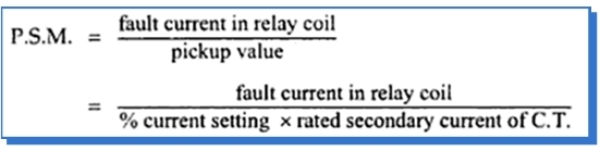
11. Plug Setting
Multiplier (P.S.M.) : The ratio of actual fault current in the
relay
coil to the pickup current is called plug setting multiplier (P.S.M.)
Mathematically it can be expressed as,
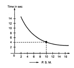
12. Time/P.S.M. Curve : For a relay, a curve showing
relation between time and
plug-setting multiplier is provided which is called time/P.S.M. curve.
A
typical curve for a relay is shown in the Fig. 2.
|
|
|
Fig. 2 Time / P.S.M. curve |
It can be observed that for low values of overcurrents the operating
time
varies inversely with the current. But as the current increases and
approaches
upto 20 times its rated value then then the tome becomes almost
constant. This
type of characteristics is necessary to ensure discrimination on very
high
fault currents flowing through healthy part of the system.
Using this curve and time-setting multiplier, the actual time of
operation of a
relay can be obtained. For example, the time in seconds corresponding
to P.S.M.
of 10 is 4 seconds as
shown in the Fig. 2. Multiplying this by a time-setting
multiplier, actual time of operation can be obtained.
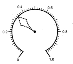
13. Time-setting
Multiplier : Similar to current setting, a relay is provided
with a
feature with which its time of operation can be controlled. This
feature is
known as time-setting multiplier. Its dial is calibrated from 0 to 1 in
steps
of 0.05 as shown in the Fig. 3.
|
|
|
Fig. 3 Time-setting multiplier |
The value of time-setting multiplier along with the time obtained from
time/P.S.M. curve decides the actual time of operation of the relay.
For
example if time-setting multiplier is selected as 0.2 while time
corresponding
to P.S.M. of 10 is 4 seconds
then,
Actual time of operation = time in seconds x time-setting multiplier
= 4 x 0.2 = 0.8 seconds
14. Trip
Circuit : The opening operation of circuit breaker is
controlled by a
circuit which consists of trip coil, relay contacts, auxiliary switch,
battery
supply etc. which is called trip circuit.
15. Earth
Fault : The fault involving earth is called earth fault. The
examples
of earth fault are single line to ground fault, double line to ground
fault etc.
16. Phase
Fault : The fault which does not involve earth is called phase
fault.
The example is line to line fault.
17. Protective
Scheme : The combination of various protective systems
covering a
particular protective zone for a particular equipment is called
protective
scheme. For example a generator may be provided with protective system
like
overcurrent, differential, earth fault etc. The combination of all
these
systems is called generator protective scheme.
18. Protective
System : The combination of circuit breakers, trip circuits,
C.T. and
other protective relaying equipments is called protective system.
19. Unit
Protection : A protective system in which the protection zone
is
clearly defined by the C.T. boundaries is called unit protection. Such
systems
work for internal faults only.
20. Reach :
The limiting distance in which protective system responds to the faults
is
called reach of the protective system. The operation beyond the set
distance is
called over-reach while failure of distance relay within set distance
is called
under-reach.