The Mini SSTC
迷你特斯拉线圈
Page Created:
创建时间:
Updated:
最后编辑时间:
I built this small coil in about 1 day of work. Its small and relatively safe. It produces up to 7" of spark, though this is limited to my small heatsinks getting too warm. If one was to copy the design but use larger heatsinks, the power could be much greater. Please scroll down to the end of the page to see the finalized schematic!
我用了大约一天的时间来制作这个小线圈。它很小,而且十分安全。尽管受到我发烫的小散热片限制,它还是放出了大约
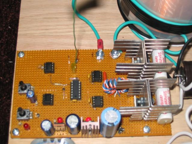
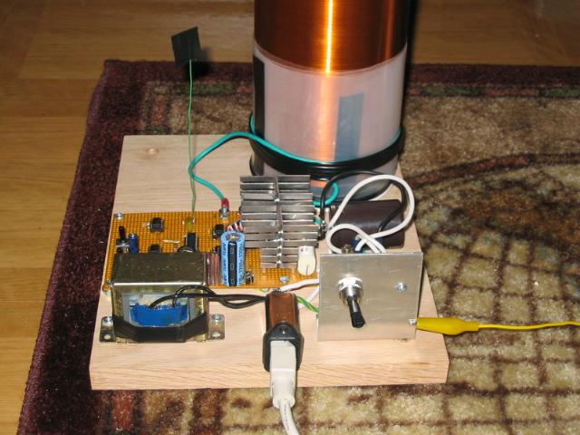
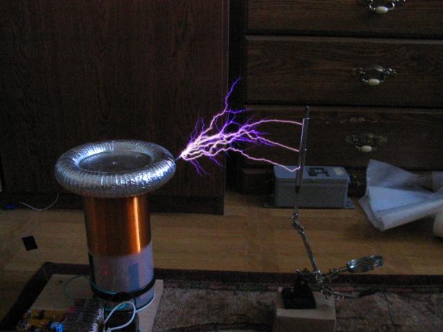
Here are some pictures of the original setup. It worked well but needed a really long antenna to work properly. See the updates for the slightly revised version.
这是早期结构的一些照片。它工作得很好,但是为了保证正常工作,需要一个相当长的天线。看看做过少许改动的最新版本。


Schematic (not final, see end of page)
原理图(不是最终版本,请看页面的最后)
Update
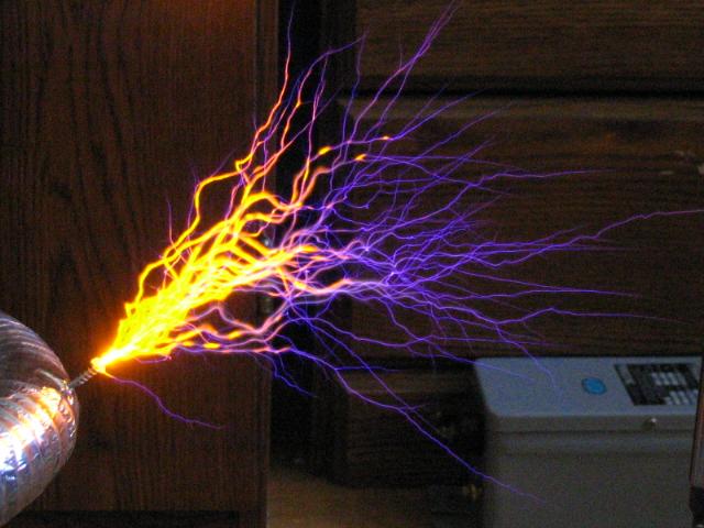
I removed 2 primary turns for a total of just 4 turns. This surprisingly helped with heating problems of the MOSFETs! I also removed the toroid and now just have a wire pointing off the edge of the coil. The coil runs much happier now. The heatsinks have yet to get overheated. Also, these changes brought about 7" sparks (compared with 6" previously). Here are some snapshots of the new setup and the various sparks this little coil can create.
我去掉了初级线圈的两圈,因为总共只需要四圈就可以了。令人惊喜的是,这个改动大大环节了MOSFET(互补金属氧化物半导体场效应晶体管——译者注)。我还去掉了圆环(指放电顶端——译者注),只留下了一根金属丝。这时,线圈运行得更加令人兴奋。散热器也过热了。然而,这些改动得到了
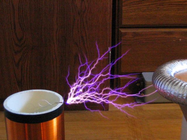
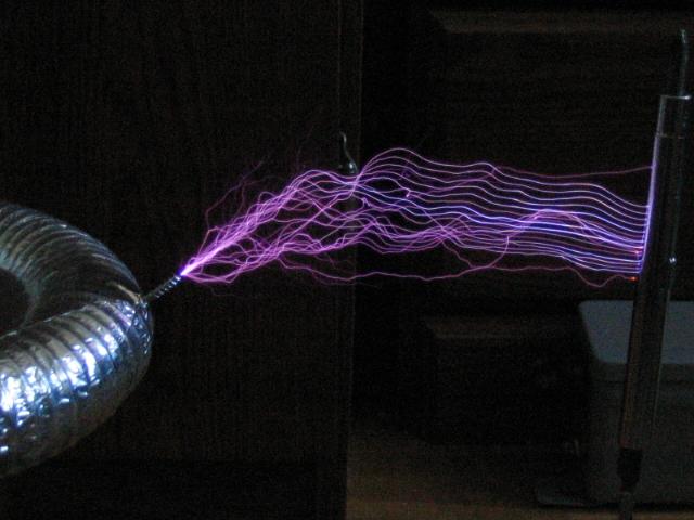
 Here the coil is operating
with a moderate pulse width and rate.
Here the coil is operating
with a moderate pulse width and rate.
线圈被控制在适中的脉宽(应该是指灭弧器的脉宽——译者注)。
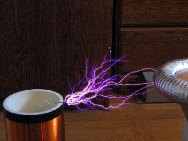
 Here the coil is running
at a low pulse rate and a low duty cycle.
Here the coil is running
at a low pulse rate and a low duty cycle.
线圈运行在更低的脉宽和更低的占空比。


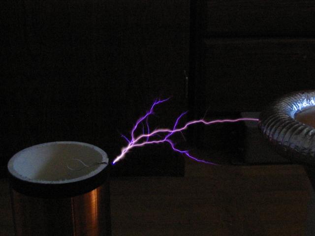
 Now the pulse rate is maxed
but still a low on time.
Now the pulse rate is maxed
but still a low on time.
脉宽调整到最高,但是曝光时间短。

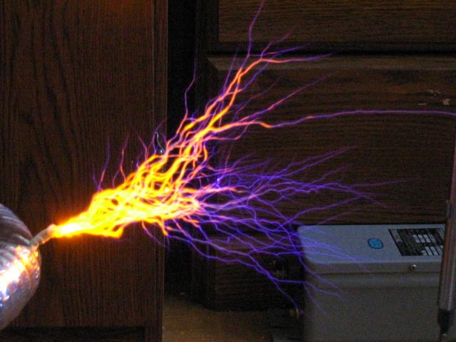
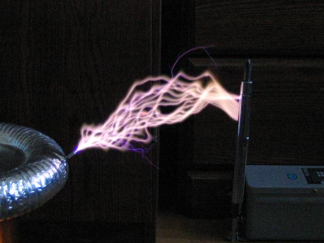 Low pulse rate, but now
the duty cycle is a bit higher, notice the thickness.
Low pulse rate, but now
the duty cycle is a bit higher, notice the thickness.
低脉宽,但是占空比非常大,注意一下电弧的宽度。
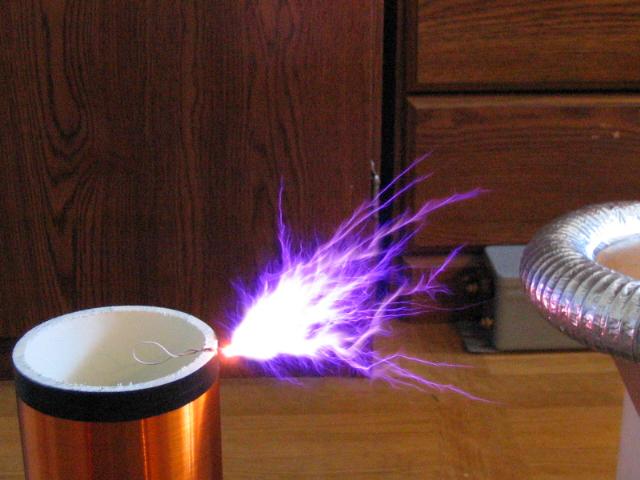
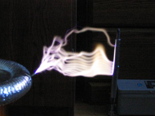 The highest duty cycle at
a low pulse rate produces flame like discharges that do burn things easily.
The highest duty cycle at
a low pulse rate produces flame like discharges that do burn things easily.
最大的占空比和低脉宽制造了像火焰一样的效果,小心不要被烧伤。
How the coil works
线圈的工作原理
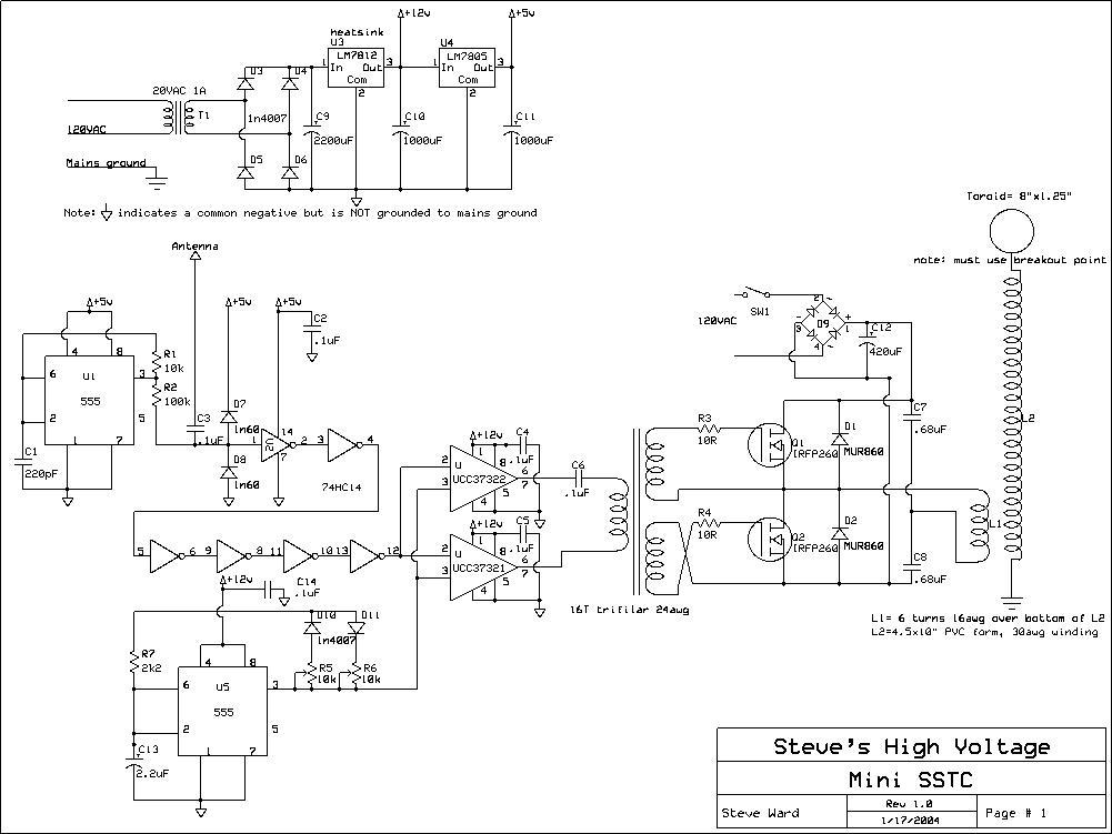
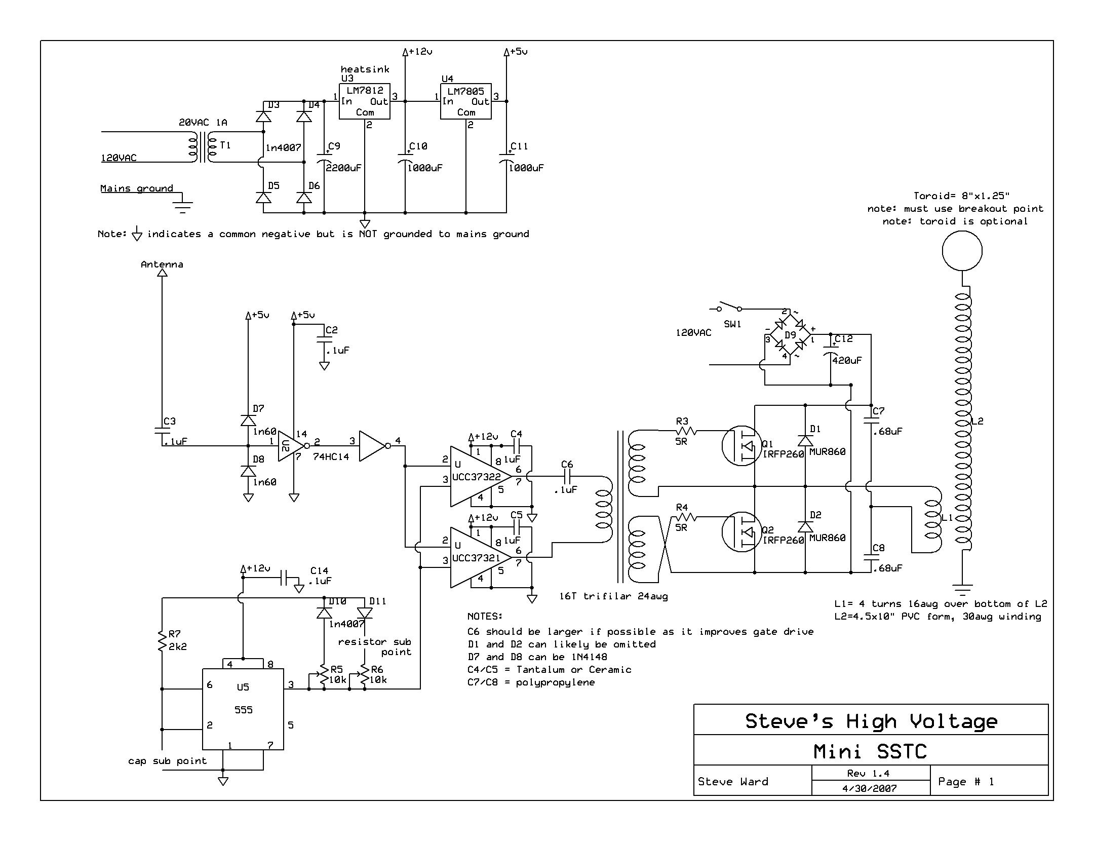
Here is an overview of the schematic and how the coil
operates. In the top of the schematic we see the low voltage power supply
section composed of a small transformer, 4 diodes, some caps and voltage
regulators. The 7812 gives 12V at about
这里叙述原理图和线圈的工作过程。在图片的上方,可以看到由小变压器构成的低压电源,有四个二极管,几个电容和几个线性稳压器。7812可以提供12V的电压和
(理解这段话叙述的原理即可,因为这段话叙述的是不够完善的版本,这个版本要比最终版本复杂。这个版本使用了一个555来引发振荡,会和反馈天线的信号冲突,可能造成不好的影响——译者注)
More Updates:
更多的更新:
I'm adding an additional schematic that shows the latest revisions. The largest change (and by far the coolest!) is the sub points added into the schematic around U5. By allowing these 2 values to be changed an amazing variety of spark appearances can be had ranging from spark gap coils to a big flaming torch. Observe the new changes
我给最新版本增加了一些附加的部分。最大的修改(这是到目前为止最酷的!)就是在子点加入了U5。改变了这两个值的结果便是,它产生了像SGTC一样的大火(实际上是等离子火焰——译者注),就像燃烧的火把。请查看最新的改动。
Revised Schematic (not final, see end of page)
修改后的原理图(不是最终版本,请看页面最下方)

Here are some substitutions I have tried so far
这是最近我刚刚试过的一些替代方案
|
Capacitor 电容 |
Resistor 电阻 |
Spark Appearance 电弧的表现 |
|
2.2uf |
0-10k |
As seen in the pictures above (this is the original configuration) 像上述的图片一样(最初的配置) |
|
2.2uf |
10Meg |
Very slow rep rate allows the study of individual spark formations (没看明白这句话——译者注) |
|
100uf |
0 |
Allows for a pulsing flame spark, very interesting and extremely hot (I received an RF burn from touching the output for just one pulse) 一个简短的火花,非常有意思,而且极其烫[我仅仅摸了一下输出,便被烧伤了(应该不是严重烧伤,手上会出现一个黑点——译者注)] |
|
.1uF |
0-10k |
Screaming tendrils of purple arcs. Noticeable ozone production. Very similar to a small spark gap coil running at high bps. Excellent banjo effect! 尖叫的紫色电弧。明显产生了臭氧。像一个小SGTC工作在高BPS(Burst Per Second,衡量每秒灭弧的次数的量——译者注)。非常棒的效果! |
|
.1uF |
10Meg |
A nice snapping spark ranging in thickness from extremely thin to moderately bright. Similar to a single shot SGTC. 非常细的电弧。很像SGTC打火一次的效果。 |
|
1000pF |
100k |
Arcs similar to a flyback. Short in length and dim until you draw the spark. 电弧很像反激变换器(开关电源的一种形式,能产生高电压——译者注)的效果。减小长度和宽度直到你找到电弧为止。 |
There are just so many awesome effects possible from the interrupter. If one does not experiment, he is missing out! I will try to get pics of each configuration later on.
这只是灭弧器产生的奇特效果的一小部分。如果你不尝试,就会失去机会!稍后我将会得到修改配置后的照片。
I made another change to the circuit that improves some things. It seems the coil will work fine without U1 (the 555) even installed! Basically, when the driver chips are enabled, the inverting chip will send a short pulse to the MOSFETs causing the oscillation to start without any problem. The fact that there is only 1 signal going to the 74hc14 means there is no room for conflict here. This ALSO means that the feedback is stronger... shorter antenna! Now the coil will happily run WITH the toroid and produce up to 8" sparks now. Here is the revised schematic:
我对电路做了一些修改,优化了某些东西。看起来,线圈即使没有U1(555)也是没有问题的!实际上,当驱动芯片被触发时,反相芯片将给MOSFET发动一个短脉冲,这个脉冲将会引发振荡二部引起任何问题。事实上,只有一个信号输入到74HC14将会避免信号之间的冲突(两个信号同时输入可能造成不大好的影响——译者注)。非常值得一提的是,这意味着我们可以使用一个更短的天线!现在,这个线圈的顶端将会令人欣喜地产生
Revision 3 (not final, see end of page)
第三次修改(不是最终版本,请看页面最下方)

Here we add some wetted salt to the breakout point:
我们给电弧喷出的点涂抹一些盐溶液(焰色反应——译者注):
After having this project out for a few years I've received quite a response from many other amateurs who have copied the design successfully. But, I very often get the same questions over and over. In particularly "why did you series up all 6 inverter gates?". At the time I built this coil I was still pretty new to electronics, so I didn't see the harm in it, and it was easy to wire, but now I realize the extra gates add unwanted delays, so this last version of the schematic has fixed that part. I also reduced the value of the gate resistors... I'm tempted to say leave them out all together, but 5 ohms should be safe. Its also possible to completely eliminate the 74HC14 and feed the antenna directly to the UCC37321/2 gate driver inputs, but this might not work as reliably for some people, so experiment at your own risk.
后来的几年里,我收到了很多仿制成功的爱好者的回复。但是,我总是被问到同一个问题:“你为什么要把6个非门全都串联起来?”当我制作这个线圈时,我还是一个新的电子爱好者,所以我没有发现它的危害,而且这是很容易就能连在一起的,但是我现在意识到,额外的门会带来不必要的延时,所以最终版本解决了这个问题。我还减小了MOSFET门极上的电阻值……我不得不说,我想把它们全部省掉,但是有了5Ω电阻应该比较安全。将74HC14省掉,直接将反馈输入到UCC37321/2似乎也是可以的,但是这样有时可能不会很可靠,所以你恐怕要冒着风险来测试这个方案。
Final Schematic (use this one to build it!)
最终的原理图(请用这一个原理图来制造线圈!)
(英语水平有限,这里面可能会出现一些小错误,但是整体应该是正确的——译者注)